
A maglev amusement drive system may use magnetic thrust while wheels carry and guide the vehicle. The term alone does not establish actual levitation.
For technical evaluators, this distinction shapes supplier comparisons, infrastructure requirements, control architecture, and maintenance planning. Magnetic propulsion does not automatically mean magnetic suspension or guidance.
The first evaluation step is therefore straightforward: identify what supports the vehicle, what constrains its movement, and what produces acceleration, braking, and station positioning.
This guide separates those functions and explains the evidence needed to assess ride integration, failure behavior, energy demand, maintainability, and the credibility of supplier proposals.
Does the Vehicle Actually Levitate, or Do Wheels Carry It?
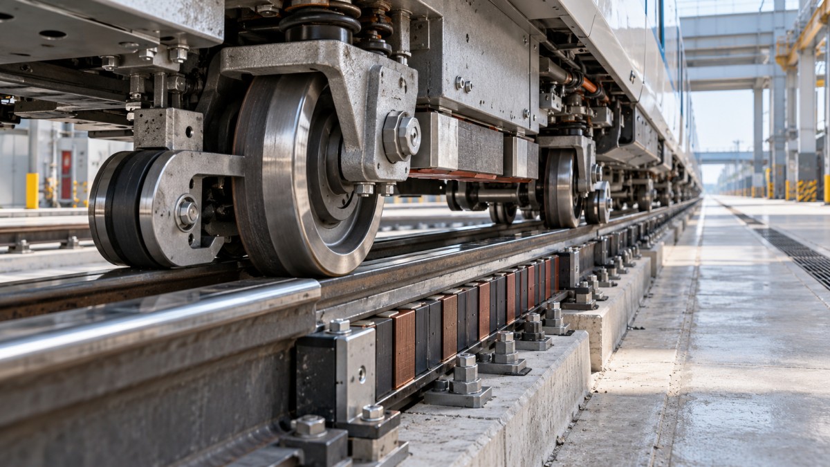
Ask suppliers for a vehicle cross section showing every load path. Marketing descriptions cannot establish whether magnets provide lift, propulsion, guidance, or some combination.
In a wheel-supported LSM installation, running wheels carry normal vertical loads. Depending on the design, separate guide and upstop wheels constrain lateral movement and uplift.
The linear synchronous motor supplies longitudinal thrust through electromagnetic interaction across an air gap. It does not inherently replace those wheel assemblies or their functions.
A genuinely levitated vehicle uses magnetic forces to support its operating weight within a defined envelope. Guidance may use separate magnetic elements or mechanical interfaces.
Some systems combine magnetic support with wheels used during starting, stopping, emergencies, or maintenance. These arrangements require explicit descriptions of when each support mode applies.
Require confirmation of support behavior at rest, during normal travel, through curves, and after power loss. A single demonstration condition cannot establish the complete operating envelope.
How Does LSM Propulsion Work on an Amusement Ride?
An LSM creates a traveling magnetic field whose motion coordinates with a corresponding magnetic field on the vehicle. Their interaction produces controlled longitudinal force.
Many ride installations use powered stator sections along the track and permanent magnets on vehicles. Suppliers should identify the actual arrangement rather than assume this configuration.
Vehicle position information enables the drive to synchronize electrical excitation with motion. Position accuracy, communication timing, and control tuning influence thrust consistency and smoothness.
Designers can distribute propulsion along launch zones or selected route sections. The selected arrangement affects electrical infrastructure, vehicle equipment, access requirements, and control integration.
LSM drives can also provide controlled deceleration when designed for that duty. Whether energy returns to the supply or dissipates elsewhere depends on converter architecture.
Propulsion capability does not establish an independent stopping or holding function. Evaluate service braking, protective stopping, rollback management, and stationary restraint as distinct requirements.
Which Performance Numbers Make Supplier Comparisons Meaningful?
Compare proposals against the same vehicle mass, passenger loading, route geometry, operating cycle, and environmental conditions. Otherwise, headline speed and acceleration figures reveal little.
Request the complete force and speed envelope, including continuous and short duration ratings. Available thrust can vary with speed, temperature, voltage, and permitted duty.
Acceleration follows the net longitudinal force divided by moving mass. Motor thrust must also overcome gradient forces and resistance, including aerodynamic drag where relevant.
As an illustration, accelerating a 10,000-kilogram train at 5 meters per second squared requires 50 kilonewtons of net force before accounting for those additional loads.
At 20 meters per second, that net force represents one megawatt of instantaneous mechanical power. Electrical input also reflects losses and the additional resistance loads.
Request acceleration and jerk profiles alongside peak values. Passenger experience, restraint loading, structural response, and repeatability depend on how forces develop throughout the operating cycle.
- Duty cycle: Specify dispatch interval, consecutive launches, recovery periods, and expected operating hours so thermal limits reflect the intended attendance pattern.
- Load cases: Include empty, nominal, and maximum passenger loads, together with gradients, wind assumptions, and applicable degraded operating conditions.
- Acceptance criteria: Define speed tolerance, stopping accuracy, ride comfort limits, and repeatability over the agreed temperature and supply voltage ranges.
What Changes When Magnetic Levitation Is Real?
Actual levitation adds a support function that must remain stable under changing passenger loads, vehicle motion, structural deflection, and disturbances throughout the operating envelope.
Electromagnetic suspension commonly uses controlled attraction and requires management of an inherently unstable gap. Electrodynamic approaches have different behavior, which may include speed-dependent lift.
These categories do not describe every proposed implementation. Request the supplier's actual lift mechanism, force versus gap characteristics, stability analysis, and operating limitations directly.
Guideway tolerances become part of the suspension problem. Thermal expansion, foundation settlement, fabrication variation, and dynamic deflection can affect clearances and available magnetic forces.
Curves, banking, and vertical transitions introduce changing force requirements. Successful levitation on straight, level track does not establish suitability for the proposed ride geometry.
Require documented transitions to auxiliary support where applicable. Contact speed, landing loads, clearances, wear surfaces, and subsequent evacuation access all need defined design limits.
What Happens After a Power, Sensor, or Control Failure?
Begin with credible failure scenarios rather than general claims of redundancy. The required response depends on vehicle location, speed, occupancy, and available stopping distance.
For wheel-supported propulsion, loss of thrust can leave the train coasting or exposed to rollback. The safety concept must explain how each condition is controlled.
For levitated vehicles, a power interruption may also affect support or guidance, depending on architecture. Backup energy and mechanical support require demonstrated capacity and transitions.
Separate ordinary motion control from safety functions where the risk assessment requires it. Specify detection, decision, actuation, diagnostics, and proof testing responsibilities across subsystem boundaries.
Passive eddy current brakes can provide speed-dependent retardation, but their braking force diminishes toward standstill. They cannot alone establish stationary holding or parking security.
Ask how passengers are reached and evacuated from every credible stopping location. Suspension technology does not remove the need for access, communication, and rescue planning.
- Power interruption: Demonstrate the stopping or support sequence from the most demanding identified operating state, including available backup energy.
- Position feedback fault: Explain fault detection, thrust inhibition, and the transition to a safe condition without assuming valid position information.
- Restart: Define inspection, reset, recovery, and passenger handling requirements before the attraction can return to normal operation.
Will the Electrical and Civil Infrastructure Fit the Site?
Launch energy and peak electrical demand describe different constraints. A short launch can impose substantial instantaneous demand even when average hourly consumption appears manageable.
Request a site power study covering connection capacity, converter requirements, harmonics, voltage disturbances, earthing, and cooling. Evaluate these requirements against local utility connection conditions.
Energy storage may reduce grid peaks, but it adds equipment, controls, replacement obligations, and space requirements. Confirm its usable capacity under the proposed dispatch schedule.
Guideway and foundations must transmit propulsion reaction forces as well as vehicle loads. Magnetic attraction can introduce additional local forces even on wheel-supported systems.
Assess environmental exposure at installation level, including drainage, contamination, corrosion, ambient temperature, and access for cleaning. Enclosure ratings alone do not establish operational suitability.
Review electromagnetic compatibility across drives, sensors, communications, and nearby equipment. Passenger exposure and medical device considerations should follow applicable requirements and the project's documented assessment.
Does Reduced Contact Actually Lower Lifecycle Cost?
Wheel-supported LSM propulsion removes the need for a mechanical traction interface at the motor. Running wheels, bearings, rails, and their inspection obligations still remain.
True levitation can reduce some normal contact wear, but it introduces other inspection and maintenance requirements. Evaluate the complete attraction rather than a single component.
Ask suppliers to identify replacement intervals and inspection methods for coils, magnets, sensors, converters, cooling equipment, backup supports, and any retained wheel assemblies or bearings.
Maintenance access can dominate downtime. A failed trackside module should have a documented isolation, removal, replacement, alignment, and verification process that fits the installation.
Estimate lifecycle cost using the same operating assumptions across bids. Include energy, labor, consumables, major replacements, specialist support, spare inventory, and expected outage consequences.
Connect availability claims to achievable passenger throughput. A faster launch improves commercial capacity only when loading, restraints, block spacing, and unloading support the dispatch interval.
What Evidence Should Technical Evaluators Require Before Approval?
A useful procurement package converts descriptive claims into measurable obligations. Require suppliers to map every promised capability to a document, analysis, inspection, or acceptance test.
Reference applicable amusement ride standards, such as relevant ASTM F24 standards or EN 13814, according to jurisdiction. Identify editions, scope, and project-specific approval requirements.
Compliance claims should identify the applicable requirement and supporting evidence. A component certificate does not establish conformity of the complete ride or its integrated controls.
Request comparable operating references with disclosed geometry, loads, duty cycles, and service history. Where references are unavailable, require proportionate prototype testing and independent technical review.
- Architecture: Obtain load path drawings, propulsion and braking interfaces, support mode definitions, and responsibility assignments between vehicle, guideway, controls, and electrical suppliers.
- Verification: Agree on instrumented performance tests, fault demonstrations, thermal endurance testing, and acceptance tolerances under representative loading and environmental conditions.
- Delivery and service: Secure maintenance documentation, training, diagnostic access, spare parts commitments, software support terms, and procedures for managing later modifications.
For a maglev amusement drive system, the decisive question is which functions magnetism performs and how each function is verified under normal and fault conditions.
Wheel-supported LSM propulsion can deliver controlled acceleration without levitation. Genuine magnetic suspension warrants additional scrutiny of stability, guideway precision, auxiliary support, and recovery procedures.
Approve the architecture that meets the attraction's verified performance, safety, availability, and lifecycle requirements. Treat the word “maglev” as a starting question, never sufficient evidence.