
Search News
Industry Portal
Hot Articles
- Meghalaya Files Criminal Complaint Against Official Over Shillong Ropeway ClosureShillong ropeway closure sparks a criminal complaint as Meghalaya and KHADC dispute licensing requirements. Explore what the conflict means for the project.
- High-Pressure Ride Hydraulics: How Pressure Controls Ride MotionHigh pressure ride hydraulics rely on pressure, flow, and control working together. Explore diagnostics and design insights for smoother, safer ride motion.
- Choosing a Dark Ride Manufacturer: Capacity, Integration, and Lifecycle CostsChoosing a dark rides manufacturer? Learn how to verify capacity, clarify integration, and compare lifecycle costs to avoid costly gaps and invest with confidence.
Popular Tags
High-Pressure Ride Hydraulics: How Pressure Controls Ride Motion
auth.
Time
Click Count
In high pressure ride hydraulics, pressure creates the force needed to move or resist a load, while the flow reaching an actuator determines its speed. Pressure alone does not prescribe a ride’s acceleration or motion profile: valve behavior, load inertia, actuator geometry, fluid compressibility, and the control system all affect the result.
That distinction matters when a motion platform feels abrupt despite following its commanded position, or when a loaded axis falls behind its trajectory even though supply pressure appears adequate. The useful starting point is to compare pressure on both sides of the actuator with actual flow, position, and acceleration throughout the movement—not just to check the pump’s pressure setting.
From pressure to actuator force
A hydraulic cylinder produces force because pressure acts over an effective piston area. For a simplified double-acting cylinder, the force available in the extension direction is approximately:
F = PcapAcap − ProdArod − friction
Here, cap-side and rod-side pressures are gauge pressures, and the rod-side effective area is reduced by the rod’s cross-section. The same supply pressure therefore does not produce identical force in both directions. Retraction can have a different force margin and speed capability, even when the requested motion is symmetric.
The resulting actuator force must overcome more than the static weight of the moving assembly. It must account for inertia, mechanical friction, external loads, and the changing geometry of the linkage. On a motion base, the force in one cylinder is not simply the platform weight divided by the number of cylinders: each actuator’s contribution changes with position and orientation. Near an unfavorable linkage angle, a modest platform load can require a much larger cylinder force.
Pressure is consequently a load response as well as a supply condition. A pump may be capable of supplying high pressure, but an actuator chamber develops the pressure required by the load and circuit, subject to control and protection limits. Evaluating a ride from the nominal pump rating alone misses the chamber pressure differential that actually produces force.
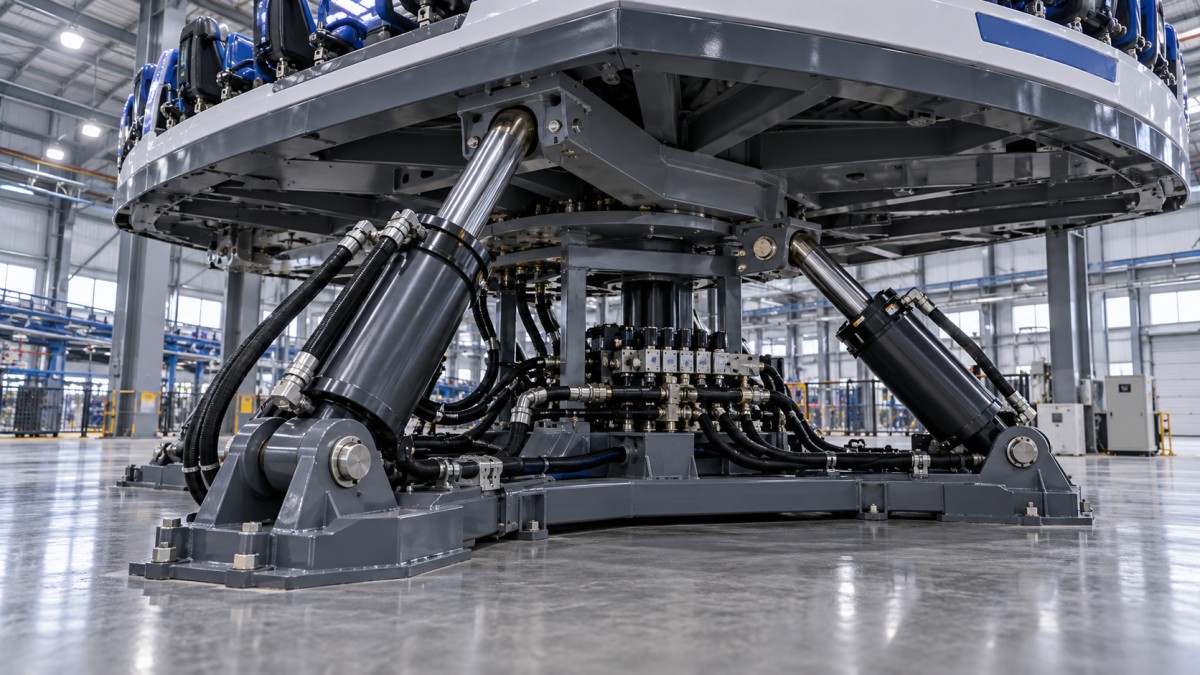
Flow, pressure drop, and the motion profile
For an ideal cylinder, velocity is approximately flow into the active chamber divided by its effective area. Real circuits add leakage and transient effects. A pump can maintain a pressure reading while a restrictive valve, undersized line, or insufficient available flow prevents the actuator from reaching the required speed.
Conversely, increasing flow capacity does not guarantee a smoother ride. A valve that opens too aggressively can produce a rapid change in acceleration, experienced as a jolt. The motion controller typically shapes position, velocity, and acceleration commands; the hydraulic circuit must then follow those commands within acceptable error. Mechanical flexibility, valve dynamics, and fluid compressibility can make the achieved acceleration differ from the programmed profile.
Supply pressure must also cover losses between the pump and actuator. Filters, hoses, manifolds, control valves, and return passages all contribute pressure drop, especially during high-flow portions of a cycle. Measure at relevant points and operating conditions: a healthy pump outlet pressure does not establish that adequate pressure is available at the cylinder port during peak demand.
Overrunning loads need special attention
When gravity or inertia drives an axis in the same direction as its commanded motion, the load can run ahead of the supplied flow. The resulting risk includes loss of controlled motion or cavitation. Depending on the design, counterbalance valves, controlled metering, or other load-control arrangements may be used to restrain the load and maintain stable pressure.
These devices must be evaluated as part of the control loop. An incorrectly selected or adjusted load-holding arrangement can cause oscillation, excessive heat, or poor tracking. Its suitability depends on load direction, actuator geometry, expected speed, and the manufacturer’s validated circuit—not on a generic pressure setting.
Reading pressure traces during a ride cycle
A useful diagnostic recording synchronizes commanded and actual position with cylinder-port pressures, supply and return pressures, and, where available, valve command and flow. Acceleration data can help connect hydraulic behavior to the motion experienced by riders. Sensor locations and sampling rates should be suitable for the transients being investigated; a slow gauge may conceal a short pressure spike.
These are diagnostic directions, not component-failure verdicts. A pressure spike, for example, may result from rapid deceleration, a control issue, or a mechanical stop. Compare the trace with the commanded motion and the expected load before deciding that the relief valve or pump is responsible.
Where accumulators fit
An accumulator stores energy in the hydraulic system and can supply flow during short demand peaks, absorb some pressure fluctuations, or support a defined controlled response after a power interruption. Its usefulness depends on the circuit, usable pressure range, gas precharge, isolation devices, and the required duty cycle. Stored volume is not all available at the operating pressure needed by the actuator.
Accumulator capacity should be checked against the actual sequence of events. If several axes demand peak flow simultaneously, the pressure may fall below the level required to track the motion even though the accumulator is charged. Repeated cycles also require enough pump capacity and time to replenish the stored energy. A larger accumulator is not a substitute for evaluating flow demand, thermal load, and control stability.
Stored hydraulic energy remains a hazard after electrical power is removed. Isolation, depressurization, verification, and maintenance procedures must account for accumulators and any trapped pressure. Never assume a stopped pump means a circuit is safe to open.
Motion control and protective functions
Precise ride motion commonly uses proportional or servo valves together with position feedback and a controller. The controller compares the requested trajectory with measured position and adjusts valve command. Pressure feedback can add useful information about load, force limits, and abnormal conditions, but pressure control by itself does not establish safe platform position or rider acceleration.
During evaluation, distinguish normal motion control from safety-related functions. A position limit used by the motion program is not automatically equivalent to an independent protective limit. Review how the design detects and responds to sensor disagreement, loss of feedback, valve faults, power loss, and hydraulic pressure outside its permitted range. The required response may differ by axis and hazard: immediate stopping, controlled deceleration, holding position, or movement to a defined safe state must be justified for the particular ride.
Stopping can itself create a hazardous load. Rapidly closing a valve on a moving, high-inertia mechanism can generate pressure transients and uncomfortable or unsafe deceleration. The assessment should therefore include the complete stop sequence, structural loads, passenger restraint assumptions, and the behavior of the hydraulic circuit—not only the time needed to interrupt a command.
Pressure limits are system limits, not just pump limits
Relief valves limit pressure under specified conditions, but their presence does not prove that every component is protected against every transient. Review the pressure ratings and placement of cylinders, hoses, fittings, manifolds, valves, and pressure-containing interfaces, including both actuator chambers. Pressure intensification can occur when a loaded cylinder or unequal effective areas create a chamber pressure higher than the supply pressure.
Operating pressure, relief settings, transient pressures, and component ratings should be considered together. The relevant design limits depend on the equipment and applicable requirements; there is no single pressure value that makes a ride safe. Hose routing, abrasion protection, mechanical support, and containment of leakage matter as well, particularly near passengers, electrical equipment, and hot surfaces.
Thermal performance is another design constraint. Energy lost across throttling valves and through leakage becomes heat. Excessive fluid temperature can alter viscosity, increase leakage, affect seals, and change control response. Check cooler capacity and reservoir conditions against the expected operating cycle, including repeated movements and warm environmental conditions rather than a single nominal cycle.
Evidence to request before accepting a design
A credible technical review connects the ride’s motion envelope to the hydraulic design and its protective functions. Useful evidence includes:
- A hydraulic schematic identifying pumps, valves, accumulators, isolation points, sensors, relief devices, and load-holding arrangements.
- Actuator force and flow calculations across the relevant motion envelope, including unfavorable geometry, payload variation, acceleration, and overrunning loads.
- Component pressure ratings and an assessment of pressure intensification and foreseeable transients.
- Motion-control specifications showing commanded versus allowable actual position, velocity, and acceleration, together with the conditions under which performance is verified.
- A documented hazard assessment and safety-function architecture covering faults, loss of power, stored energy, recovery, and maintenance isolation.
- Commissioning and inspection procedures for pressure instrumentation, leakage, temperature, protective devices, and motion behavior under representative operating conditions.
Ask which assumptions underpin each calculation and whether test measurements confirm them. A design that performs well without passengers or with a static load may respond differently across its permitted payload distribution and operating temperature range. Acceptance criteria should identify the configuration, measurements, tolerances, and responsible parties rather than relying on a general statement that the motion is smooth.
Applicable amusement-ride, machinery, and hydraulic-fluid-power requirements depend on the jurisdiction, ride type, and contractual scope. Establish the governing editions and conformity route with the project’s responsible engineering and inspection parties. Where a trace or calculation reveals an unexplained pressure transient, unstable load holding, or uncertain fault response, resolve that issue against the approved design before returning the ride to service.
Recommended News
TIME
auth.